

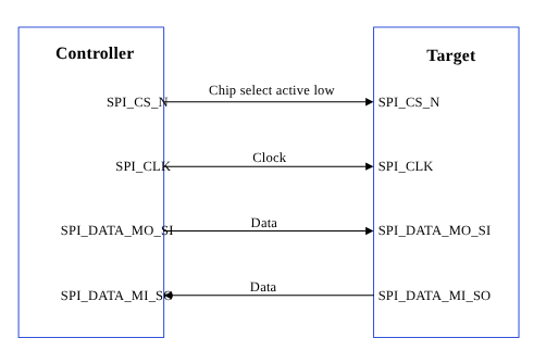
Figure : SPI data flow
The SPI core supports the bidirectional SPI standard, point-to-point, and controller-target protocol. The SPI core uses four chip‑select lines (SPI_CS#_N) to select target devices for communication. The following two data lines support the bidirectional data transfer.- SPI_DATA_MO_SI: Controller data output, target data input.
- SPI_DATA_MI_SO: Controller data input, target data output.
| Data signals | MOSI: Controller data output, target data input. |
| MISO: Controller data input, target data output. | |
| Control signals | SCLK: A clock generated by the controller and input to all targets. |
| CS: Chip-select, a target is selected when the controller asserts its CS_N signal. |
SPI features
This section explains the SPI serial engine transfer modes and the different scenarios where each mode is used. This section also describes the FIFO and DMA enabled in various subsystem SPI drivers. Table : SPI transfer modes| Subsystem | Transfer mode | Description |
|---|---|---|
| Linux |
| Supports a maximum configuration speed of 50 MHz. |
| Boot | FIFO |
|
| aDSP |
|
|
SPI interface components
This section provides information about the subsystem drivers, kernel device tree nodes, and related documentation. Table : SPI interface: Linux Table : SPI interface: Boot| File type | Description |
|---|---|
| QUP v3 serial engine configuration |
|
| Qualcomm TEE settings |
|
| File type | Description |
|---|---|
| QUP v3 serial engine configuration |
|
| Firmware configuration settings |
|
| File type | Description |
|---|---|
| QUP v3 serial engine configuration |
|
| Qualcomm TEE settings |
|
SPI APIs
SPI APIs for the following subsystems are listed in this section.- Linux:
- Boot: boot_images/boot/QcomPkg/Include/SpiApi.h
- aDSP/SDC: adsp_proc/core/api/buses/spi_api.h
SPI software device tree configuration
This section provides information on the SPI device tree configuration and documentation for the device nodes.Linux
For device SPI details, see the following DTSI files.- QCS6490 and QCS5430: https://git.linaro.org/kernel-org/linux-next.git/tree/arch/arm64/boot/dts/qcom/sc7280.dtsi
- Dragonwing IQ-9075: https://github.com/torvalds/linux/blob/master/arch/arm64/boot/dts/qcom/sa8775p.dtsi
- Dragonwing IQ-615: https://git.kernel.org/pub/scm/linux/kernel/git/qcom/linux.git/tree/arch/arm64/boot/dts/qcom/qcs615.dtsi?h=arm64-for-6.16
pinctrl configuration, see the following files.
- QCS6490 and QCS5430: https://git.linaro.org/kernel-org/linux-next.git/tree/arch/arm64/boot/dts/qcom/sc7280.dtsi
- Dragonwing IQ-9075: https://github.com/torvalds/linux/blob/master/arch/arm64/boot/dts/qcom/sa8775p.dtsi
- Dragonwing IQ-615: https://git.kernel.org/pub/scm/linux/kernel/git/qcom/linux.git/tree/arch/arm64/boot/dts/qcom/qcs615.dtsi?h=arm64-for-6.16
Documentation/devicetree/bindings/pinctrl/qcom,<chipset>-tlmm.yaml
pinctrl.dtsi.
For example:
/firmware/qualcomm-linux-spf-1-0_ap_standard_oem_nomodem/TZ.XF.5.0/trustzone_images/core/settings/buses/qup_accesscontrol/qupv3/config/<chipset>/QUPAC_Access.c. Modify the required settings if needed or see the default settings assigned for QUP v3 serial engine instances.
Following is the sample configuration for enabling the SPI.
Boot
Configure the QUP v3 settings according to the Qualcomm Linux chip product requirements in the/firmware/qualcomm-linux-spf-1-0_ap_standard_oem_nomodem/BOOT.MXF.1.0.c1/boot_images/boot/Settings/Soc/<chipset>/Core/Buses/qup_common/<chipset>-qupv3.dtsi file.
NoteTo enable the required QUP v3 serial engine, update the QUP v3 wrapper node status to
okay, and the respective serial engine node to disabled state.pinctrl definitions, see the GPIO configuration file at /firmware/qualcomm-linux-spf-1-0_ap_standard_oem_nomodem/BOOT.MXF.1.0.c1/boot_images/boot/Settings/Soc/<chipset>/Core/Buses/qup_common/<chipset>-qupv3-pinctrl.dtsi.
Sample GPIO configuration:
- In
<chipset>-qupv3-pinctrl.dtsimodify the macro with the GPIO configuration when the requirements are different from the default configuration. - For the macro definition, see the header file path at
Settings/Include/gpio-dt.h.
NoteVerify Qualcomm TEE settings before changing the unified extensible firmware interface (UEFI) configuration. Ensure that the serial engine node is in FIFO_MODE and accessible from the application processor. Verify that the loaded protocol is according to the requirement.
aDSP/SDC
The firmware loads SSC QUP during the bootup sequence of the aDSP subsystem. The configuration file is present in the aDSP build at/firmware/qualcomm-linux-spf-1-0_ap_standard_oem_nomodem/ADSP.HT.5.5.c8/adsp_proc/core/settings/buses/qup_fw/config/<chipset>/fw_devcfg.c and /firmware/qualcomm-linux-spf-1-0_ap_standard_oem_nomodem/ADSP.HT.5.5.c8/adsp_proc/core/settings/buses/qup_fw/config/<chipset>/fw_devcfg.xml.
The following configuration is a sample of the SSC QUP SE4 loaded with the SPI firmware.
/firmware/qualcomm-linux-spf-1-0_ap_standard_oem_nomodem/ADSP.HT.5.5.c8/adsp_proc/core/settings/buses/qup_common/config/<chipset>/adsp/ssc/qup_instance_mapping.c.
The default GPIO configuration can be overwritten as follows.
Qualcomm TEE
The QUP v3 access configuration settings are at/firmware/qualcomm-linux-spf-1-0_ap_standard_oem_nomodem/TZ.XF.5.0/trustzone_images/core/settings/buses/spi/qupv3/interface/spi_devcfg.h.
To enable the QUP v3 serial engine for SPI in /firmware/qualcomm-linux-spf-1-0_ap_standard_oem_nomodem/TZ.XF.5.0/trustzone_images/core/settings/buses/spi/qupv3/config/<chipset>/tz/spi_devcfg_user.h, add #define TZ_USE_SPI_X (X is the SPI serial engine number) as follows.
TZ_USE_SPI_<num> number is based on the serial number of the serial engine (starting from one). For example, if there are two QUPs: QUPV3_0 with seven serial engines and QUPV3_1 with eight serial engines, the user must enable QUPV3_2_SE2. The macro should be TZ_USE_SPI_9.
GPIO configuration: In the following example, drive strength and pull are configured according to the PIN starting index from MISO at settings/buses/spi/qupv3/config/<chipset>/tz/spi_devcfg_user.c.
/firmware/qualcomm-linux-spf-1-0_ap_standard_oem_nomodem/TZ.XF.5.0/trustzone_images/core/settings/buses/qup_accesscontrol/qupv3/config/<chipset>/QUPAC_Access.c.
SPI bringup
This section describes how to enable the Qualcomm Linux SPI drivers.Linux
To verify SPI communication with the device, kernel configuration must be enabled. TheCONFIG_SPI_SPIDEV=m setting is enabled in the corresponding <chipset> defconfig file. Enable the specific QUP v3 SPI serial engine instance in the kernel device tree.
SPI configuration
This section provides information about the SPI software driver kernel configuration and device tree node changes.Linux
The following driver kernel configurations are required to support the SPI interface.- Driver source file at https://github.com/torvalds/linux/blob/master/drivers/spi/spi-geni-qcom.c
- Kernel
defconfigfile at<workspace_path_of_LINUX_kernel_image>/sources/kernel/kernel_platform/kernel/arch/arm64/configs/qcom_defconfig
CONFIG_QCOM_GENI_SE=yCONFIG_SPI_QCOM_GENI=mCONFIG_SPI_SPIDEV=mto configure user space applicationsCONFIG_QCOM_GPI_DMA=mto enable GSI support
/arch/arm64/boot/dts/qcom/<chipset>.dtsi file.
NoteYou should compile the kernel configuration and device tree changes. After the kernel is compiled, you can load the images to the device to verify the interface. For information about interface verification, see the SPI verification section.
SPI verification
This section describes the validation procedure and test results for the SPI drivers.Linux
To cross-compile the SPI tools, do the following.- Access the SPI tool from
yocto/build-qcom-wayland/tmp-glibc/work-shared/<chipset>/kernel-source/tools/spi. For more details about the SPI tool, see https://git.kernel.org/pub/scm/linux/kernel/git/stable/linux.git/tree/tools/spi. - Install cross compiler.
- Set up the environment for cross-compilation by running the following command.
- Compile the tool by running the following command.
Verify SPI device
Verify the driver by checking fordev node (/dev/spidev1.0) in the SSH shell or use the ADB shell. For more information about how to run SSH, see the Use SSH section.
- To verify the SPI driver, do the following:
- Open the SSH shell in permissive mode or use the ADB shell.
- Mount the file system.
- Transfer files using SCP or similar tools.
For example,
scp spidev_test root@10.92.175.138:/bin. - Assign permission to execute.
- Verify an SPI device. Command format
./spidev_test -D /dev/<spidev_node>.The following output is displayed.
SPI debugging
This section describes the default logging method of the SPI software driver to enable logging the SPI transfer failures.Linux
The SPI driver logs are enabled through a dynamic debugging method. EnableCONFIG_DYNAMIC_DEBUG in <workspace_path_of_LINUX_kernel_image>/sources/kernel/kernel_platform/kernel/arch/arm64/configs/qcom_defconfig to support the dynamic debugging of the kernel drivers.
To enable and view the SPI driver logs in the kernel logs (dmesg), run the following command.
SPI examples
For information about the upstream device tree reference, see the following DTSI files.- QCS6490 and QCS5430: https://git.linaro.org/kernel-org/linux-next.git/tree/arch/arm64/boot/dts/qcom/sc7280.dtsi
- Dragonwing IQ-9075: https://github.com/torvalds/linux/blob/master/arch/arm64/boot/dts/qcom/sa8775p.dtsi
- Dragonwing IQ-615: https://git.kernel.org/pub/scm/linux/kernel/git/qcom/linux.git/tree/arch/arm64/boot/dts/qcom/qcs615.dtsi?h=arm64-for-6.16
- QCS6490 and QCS5430: https://git.linaro.org/kernel-org/linux-next.git/tree/arch/arm64/boot/dts/qcom/qcs6490-rb3gen2.dts
- Dragonwing IQ-9075: https://github.com/torvalds/linux/blob/master/arch/arm64/boot/dts/qcom/sa8775p.dtsi
- Dragonwing IQ-615: https://git.kernel.org/pub/scm/linux/kernel/git/qcom/linux.git/tree/arch/arm64/boot/dts/qcom/qcs615.dtsi?h=arm64-for-6.16